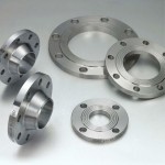
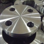
SORF Flange
Slip-on (SO) Flanges are preferred by some contractors, over the Weld-neck, because of the lower initial cost. However, this may be offset by the added cost of the two fillet welds required for proper installation. The strength of the slip-on flange is ample for it’s rating, but its life under fatigue conditions is considered to be only one-third that of the weld-neck flange.
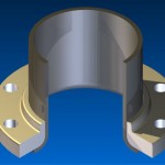
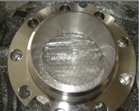
The slip-on flange may be attached to the end of a piece of pipe or to one or more ends of a pipefitting. The slip-on flange is positioned so the inserted end of the pipe or fitting is set back or short of the flange face by the thickness of the pipe wall plus 1/8 of an inch. This allows for a fillet weld inside the SO flange equal to the thickness of the pipe without doing any damage to the flange face. The back or outside of the flange is also welded with a fillet weld.
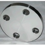
A variation of the Slip-on flange also exists. This is the Slip-on Reducing Flange. This is simply a larger (say a 14″) Slip-on flange blank that, instead of the Center (pipe) hole being cut out (or drilled out) for 14″ pipe it is cut out for a 6″ pipe. The SO Reducing flange is basically used for reducing the line size where space limitations will not allow the length of a weld neck flange and reducer combination. The use of the Slip-on Reducing Flange should only be used where the flow direction is from the smaller size into the larger size.
These Flanges are available in the following range.
Duplex Stainless Steel: UNS S31803, UNS S32750
Carbon Steel: ASTM A105,
Alloy Steel: ASTM A182 F1, F11, F22, F5, F9, F91
Nickel Alloys: Monel 400 & 500, Inconel 600 & 625, Incoloy 800, 825, Hastelloy C22, C276
Copper Alloys: Copper, Brass & Gunmetal
Size: 1/8″ NB To 48″NB and also Custom Specific.
Class: 150#, 300#, 400#, 600#, 900#, 1500#, 2500#.
Dimensional Standard ANSI: ANSI B16.5, ANSI B16.47, MSS SP44, ANSI B16.36, ANSI B16.48
DIN: DIN2527, DIN2566, DIN2573, DIN2576, DIN2641, DIN2642, DIN2655, DIN2656, DIN2627, DIN2628, DIN2629, DIN 2631, DIN2632, DIN2633, DIN2634, DIN2635, DIN2636, DIN2637, DIN2638, DIN2673
B.S: BS 4504, BS4504, BS1560, BS10
| DIMENSIONS of CLASS 150 FLANGES AS PER ANSI B 16.5 | ||||||||||
| NB | A | D | B | G | K | E | H | L | No.of Holes | |
| 1/2 ” | 15 | 30.2 | 88.9 | 11.1 | 34.9 | 60.3 | 22.3 | 15.9 | 15.9 | 4 |
| 3/4 ” | 20 | 38.1 | 98.4 | 12.7 | 42.9 | 69.8 | 27.7 | 15.9 | 15.9 | 4 |
| 1” | 25 | 49.2 | 107.9 | 14.3 | 50.8 | 79.4 | 34.5 | 17.5 | 15.9 | 4 |
| 1 1/4 ” | 32 | 58.7 | 117.5 | 15.9 | 63.5 | 88.9 | 43.2 | 20.6 | 15.9 | 4 |
| 1 1/2 ” | 40 | 65.1 | 127.0 | 17.5 | 73.0 | 98.4 | 49.5 | 22.2 | 15.9 | 4 |
| 2” | 50 | 77.8 | 152.4 | 19.0 | 92.1 | 120.6 | 62.0 | 25.4 | 19.0 | 4 |
| 2 1/2 ” | 65 | 90.5 | 177.8 | 22.2 | 104.8 | 139.7 | 74.7 | 28.6 | 19.0 | 4 |
| 3” | 80 | 107.9 | 190.5 | 23.8 | 127.0 | 152.4 | 90.7 | 30.2 | 19.0 | 4 |
| 4” | 100 | 134.9 | 230.0 | 23.8 | 157.2 | 190.5 | 116.1 | 33.3 | 19.0 | 8 |
| 5” | 125 | 163.5 | 254.0 | 23.8 | 185.7 | 215.9 | 143.8 | 36.5 | 22.2 | 8 |
| 6” | 150 | 192.1 | 279.4 | 25.4 | 215.9 | 241.3 | 170.7 | 39.7 | 22.2 | 8 |
| 8” | 200 | 246.1 | 342.9 | 28.6 | 269.9 | 298.4 | 221.5 | 44.4 | 22.2 | 8 |
| 10” | 250 | 304.8 | 406.4 | 30.2 | 323.8 | 361.9 | 276.3 | 49.2 | 25.4 | 12 |
| 12” | 300 | 365.1 | 482.6 | 31.8 | 381.0 | 431.8 | 327.1 | 55.6 | 25.4 | 12 |
| 14” | 350 | 400.0 | 533.4 | 34.9 | 412.7 | 476.2 | 359.1 | 57.1 | 28.6 | 12 |
| 16” | 400 | 457.2 | 596.9 | 36.5 | 469.9 | 539.7 | 410.5 | 63.5 | 28.6 | 16 |
| 18” | 450 | 504.8 | 635.0 | 39.7 | 533.4 | 577.8 | 461.8 | 68.3 | 31.7 | 16 |
| 20” | 500 | 558.8 | 698.5 | 42.9 | 584.2 | 635.0 | 513.1 | 73.0 | 31.7 | 20 |
| 24” | 600 | 663.6 | 812.8 | 47.6 | 692.1 | 749.3 | 615.9 | 82.5 | 34.9 | 20 |
| DIMENSIONS of CLASS 300 FLANGES AS PER ANSI B 16.5 | ||||||||||
| NB | A | D | B | G | K | E | H | L | No. of Holes | |
| 1/2 ” | 15 | 38.1 | 95.2 | 14.3 | 34.9 | 66.7 | 22.3 | 22.2 | 15.9 | 4 |
| 3/4 ” | 20 | 47.6 | 117.5 | 15.9 | 42.9 | 82.5 | 27.7 | 25.4 | 19.0 | 4 |
| 1” | 25 | 54.0 | 123.8 | 17.5 | 50.8 | 88.9 | 34.5 | 27.0 | 19.0 | 4 |
| 1 1/4 ” | 32 | 63.5 | 133.3 | 19.0 | 63.5 | 98.4 | 43.2 | 27.0 | 19.0 | 4 |
| 1 1/2 ” | 40 | 69.8 | 155.6 | 20.6 | 73.0 | 114.3 | 49.5 | 30.2 | 22.2 | 4 |
| 2” | 50 | 84.1 | 165.1 | 22.2 | 92.1 | 127.0 | 62.0 | 33.3 | 19.0 | 8 |
| 2 1/2 ” | 65 | 100.0 | 190.5 | 25.4 | 104.8 | 149.2 | 74.7 | 38.1 | 22.2 | 8 |
| 3” | 80 | 117.5 | 209.5 | 28.6 | 127.0 | 168.3 | 90.7 | 42.9 | 22.2 | 8 |
| 4” | 100 | 146.0 | 254.0 | 31.8 | 157.2 | 200.0 | 116.1 | 47.6 | 22.2 | 8 |
| 5” | 125 | 177.8 | 279.4 | 34.9 | 185.7 | 234.9 | 143.8 | 50.8 | 22.2 | 8 |
| 6” | 150 | 206.4 | 317.5 | 36.5 | 215.9 | 269.9 | 170.7 | 52.4 | 22.2 | 12 |
| 8” | 200 | 260.3 | 381.0 | 41.3 | 269.9 | 330.2 | 221.5 | 61.9 | 25.4 | 12 |
| 10” | 250 | 320.7 | 444.5 | 47.6 | 323.8 | 387.3 | 276.3 | 66.7 | 28.6 | 16 |
| 12” | 300 | 374.6 | 520.7 | 50.8 | 381.0 | 450.8 | 327.1 | 73.0 | 31.7 | 16 |
| 14” | 350 | 425.4 | 584.2 | 54.0 | 412.7 | 514.3 | 359.1 | 76.2 | 31.7 | 20 |
| 16” | 400 | 482.6 | 647.7 | 57.2 | 469.9 | 571.5 | 410.5 | 82.5 | 34.9 | 20 |
| 18” | 450 | 533.4 | 711.2 | 60.3 | 533.4 | 628.5 | 461.8 | 88.9 | 34.9 | 24 |
| 20” | 500 | 587.4 | 774.7 | 63.5 | 584.2 | 685.8 | 513.1 | 95.2 | 34.9 | 24 |
| 24” | 600 | 701.7 | 914.4 | 69.8 | 692.1 | 812.8 | 615.9 | 106.4 | 41.3 | 24 |
| DIMENSIONS of CLASS 600 FLANGES AS PER ANSI B 16.5 | ||||||||||
| NB | A | D | B | G | K | E | H | L | No. of Holes | |
| 1/2 ” | 15 | 38.1 | 95.2 | 14.3 | 34.9 | 66.7 | 22.3 | 22.2 | 15.9 | 4 |
| 3/4 ” | 20 | 47.6 | 117.5 | 15.9 | 42.9 | 82.5 | 27.7 | 25.4 | 19.0 | 4 |
| 1” | 25 | 54.0 | 123.8 | 17.5 | 50.8 | 88.9 | 34.5 | 27.0 | 19.0 | 4 |
| 1 1/4 ” | 32 | 63.5 | 133.3 | 20.6 | 63.5 | 98.4 | 43.2 | 28.6 | 19.0 | 4 |
| 1 1/2 ” | 40 | 69.8 | 155.6 | 22.2 | 73.0 | 114.3 | 49.5 | 31.7 | 22.2 | 4 |
| 2” | 50 | 84.1 | 165.1 | 25.4 | 92.1 | 127.0 | 62.0 | 36.5 | 19.0 | 8 |
| 2 1/2 ” | 65 | 100.0 | 190.5 | 28.6 | 104.8 | 149.2 | 74.7 | 41.3 | 22.2 | 8 |
| 3” | 80 | 117.5 | 209.5 | 31.8 | 127.0 | 168.3 | 90.7 | 46.0 | 22.2 | 8 |
| 4” | 100 | 152.4 | 273.0 | 38.1 | 157.2 | 215.9 | 116.1 | 54.0 | 25.4 | 8 |
| 5” | 125 | 188.9 | 330.2 | 44.4 | 185.7 | 266.7 | 143.8 | 60.3 | 28.6 | 8 |
| 6” | 150 | 222.2 | 355.6 | 47.6 | 215.9 | 292.1 | 170.7 | 66.7 | 28.6 | 12 |
| 8” | 200 | 273.0 | 419.1 | 55.6 | 269.9 | 349.2 | 221.5 | 76.2 | 31.7 | 12 |
| 10” | 250 | 342.9 | 508.0 | 63.5 | 323.8 | 431.8 | 276.3 | 85.7 | 34.9 | 16 |
| 12” | 300 | 400.0 | 558.8 | 66.7 | 381.0 | 488.9 | 327.1 | 92.1 | 34.9 | 20 |
| 14” | 350 | 431.8 | 603.2 | 69.9 | 412.7 | 527.0 | 359.1 | 93.7 | 38.1 | 20 |
| 16” | 400 | 495.3 | 685.8 | 75.2 | 469.9 | 603.2 | 410.5 | 106.4 | 41.3 | 20 |
| 18” | 450 | 546.0 | 742.9 | 82.6 | 533.4 | 654.0 | 461.8 | 117.5 | 44.4 | 20 |
| 20” | 500 | 609.6 | 812.8 | 88.9 | 584.2 | 723.9 | 513.1 | 127.0 | 44.4 | 24 |
| 24” | 600 | 717.6 | 939.8 | 101.6 | 692.1 | 838.2 | 615.9 | 139.7 | 50.8 | 24 |